Building Dosing System With Arduino Controller

kapelan

Member
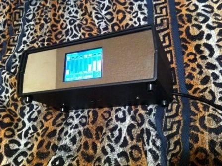
I want to build a dosing system, decided to use these dosing pumps.
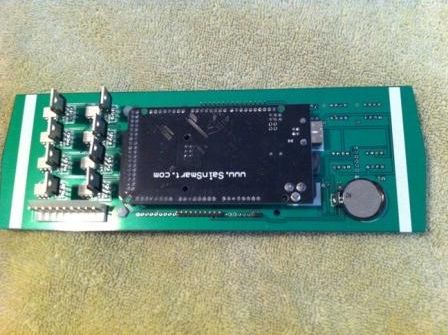
Already have a controller for it.
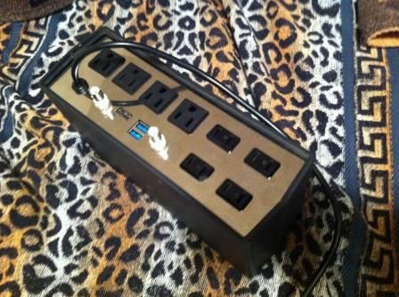
As usually when you have all parts the question is coming how to do assembly neat?
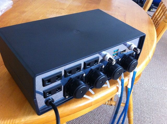
So I have pumps, box, controller ... and now need a laser cutting service to cut stainless steel
Does anybody know who can do it?
$_35.JPG
 

kapelan

Member
how did you cut panels ?
I already have a controller with timers:
ControllerBox_front_zps0nwsczmr.jpg

this is back panel:
ControllerBox_back_zps01fci6ir.jpg


And I'd like to cut new back panel and install there these pumps instead of 4 sockets.
 

kapelan

Member
I have a thread in the DIY section using that pump
In a first place this controller was created for LED.
So it can be setup any spectrum as needed:

Spectrum can be changed during the day as well:

Now added dosers:

So need a new back panel.
 

TORX

Administrator
Staff member
Website Admin
I used a good old fashion dremel, files and elbow grease. Those pumps work great and if you read me thread, it shows that they do dose reliably over time. Only it is hard to just dose a little. Good luck with the build. Just remember, a doser is only as good as the programming.
 

kapelan

Member
Started new version.
Planning change:
- replace ORP with one more PH channel. So it will be 2 PH channels
- add switch Fahrenheit/Celsius
- Some UI change: remove not used timers from the screen and use a button to "add new"
Thinking what else should be added/improved.
Any suggestion?
What do we need to automate the system?
 

KBennett

Member
I'm doing the same thing. I find that even with optically isolated relay modules my arduino freezes when running these pumps. Can't figure out how to solve it.
 

KBennett

Member
Tried that. The issue is during steady run, not when it stops. Tried a 100uf cap across it too. Even tried a resistor in series with the output to lower current draw on the output. Nothing works. I'm using i2c and onewire. I think the extra current draw is somehow causing the communication to time out.
 

kapelan

Member
Tried that. The issue is during steady run, not when it stops. Tried a 100uf cap across it too. Even tried a resistor in series with the output to lower current draw on the output. Nothing works. I'm using i2c and onewire. I think the extra current draw is somehow causing the communication to time out.
which power supply are you using?
 

KBennett

Member
I tried several different configurations with different supplies. I have 3 separate 24V supplies and I use little step down chips for 5 and 12 volts. VCc on the relay board is totally separate... I'm going to try running them of a dedicated uno next...
 

KBennett

Member
No name 24 volt 5 amp power supplies. Pretty standardized model I think.
It runs for varying times before freezing. From a few seconds to several minutes.
 

kapelan

Member
PCB that hold everything (RTC, relay ....) was designed.
it looks like this: (solid state relay on the right)
Controller_Back_zps2cf8bd8c.jpg


KBennett

Member
Oh. I Have a sain smart solid state relay board for my ac pumps. it can turn the DC pumps on but can't interrupt the current. I assume it uses thyristors or instead of mosfets.
 
Top